S5 for Windows ® Version 7 – 10018
S5 for Windows® provides the tools to create, modify, test, and document programs for programmable logic controllers (PLCs).

S5 for Windows ® Version 7 – 10018
S5 for Windows® provides the tools to create, modify, test, and document programs for programmable logic controllers (PLCs).
- MPI
- PPI
- Profibus (DP, FDL, FMS, PA)
- RFC1006, ISO Over TCP
- Ethernet
- Field Bus
- Serial
- IBHsoftec S5 and S7 for Windows
New in version 7:
- OsziCam
- Status recorder
- LogView
- Intelligent input assistance
- Online with SIMATIC S5 via SINEC L2
- Online with SIMATIC S5 via H1
- Call of the COM STEP5 packages in
Windows XP (32/64 bit)
Windows Vista (32/64 bit)
Windows 7 (32 /64 Bits)
Windows 8 (32/64 Bits)
Windows 10 (32/64 Bits)
Windows 11 (64 Bits)
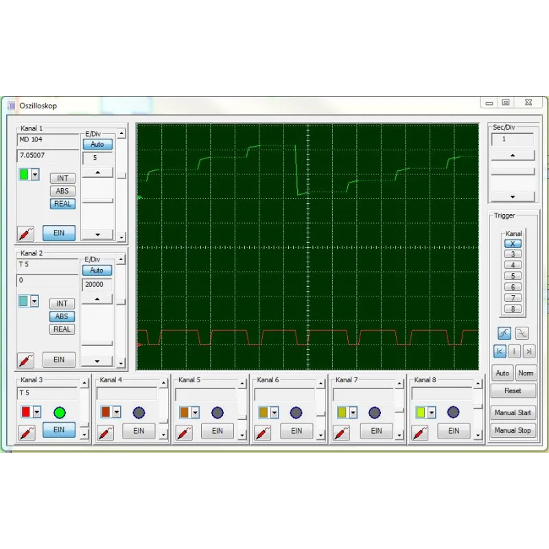
S5 for Windows provides the tools to create, modify, test, and document programs for programmable logic controllers (PLCs). S5 for Windows is designed to program the Siemens SIMATIC S5 PLC family with STEP5. Function block diagram (FBD), ladder diagram (LAD), and instruction list (STL) are used as presentations for S5. Existing S5 programs can be edited directly without importing/exporting. S5 for Windows is compatible with the original Siemens programming unit. For automatic troubleshooting, the functions of the S5 Doctor are also integrated.
A user-friendly editor is integrated for creating and editing symbolic tables. It is possible to search and replace according to any criteria, as well as to rewire. Syntax verification is integrated. The new and convenient multi-segment editor for creating instruction lists, function block diagrams, and contact diagrams also allows the representation of complex functions. The focus has been on ease of use with the mouse and/or keyboard. Cross-references and/or corresponding symbol files are displayed with the correct addresses. In this window, the symbol file can be edited simultaneously. The assignment of new addresses with syntax verification is integrated. Account status lists are created with the convenience of the integrated editor. The Windows clipboard can be used for program manipulations or configurations anywhere. Declaration lists can be transformed into function block diagrams or ladder diagrams, to the extent that they are viewable. The visualization of function block diagrams and ladder diagrams in the form of state declaration lists is always possible. OsciCAM allows the analysis of motion processes by synchronizing previously recorded videos and process signals. Recorded videos can be displayed in a synchronized manner to process signals and a recorded block status of the PLC with time stamp. With the Statusrecorder, dynamic procedures can be explored by means of the subsequent analysis of the block status frame by frame. Statusrecorder records the block status and displays it with a time stamp, which allows subsequent switching between the STL, CSF, and LAD presentations. PLC block status from the Statusrecorder. With the Oscilloscope function, the diagnostic capabilities of the programming system are further enhanced. improved. Dynamic processes can be monitored and analyzed on an integrated screen, with an adapted appearance of the front panel of an oscilloscope. Pointing to I/O signals with a virtual test probe is sufficient to monitor multiple signals within the virtual oscilloscope. Signal recording can be stopped at any time to perform a more detailed investigation of the machine failure. In addition to observing the I/O signals, the status of the local variables can also be observed at a defined position of program execution, simply by pointing to the variable with the test probe in block status. This is only possible thanks to the integration into the S5 programming system for Windows. The recorded data can also be saved for further investigation, for archiving purposes or to send the information by e-mail. A user-friendly editor is integrated for creating and editing symbolic tables. It is possible to search and replace according to any criteria, as well as to rewire. Syntax verification is integrated. The new and convenient multi-segment editor for creating instruction lists, function block diagrams, and contact diagrams also allows the representation of complex functions. The focus has been on ease of use with the mouse and/or keyboard. Cross-references and/or corresponding symbol files are displayed with the correct addresses. In this window, the symbol file can be edited simultaneously. The assignment of new addresses with syntax verification is integrated. Account status lists are created with the convenience of the integrated editor. The Windows clipboard can be used for program manipulations or configurations anywhere. Declaration lists can be transformed into function block diagrams or ladder diagrams, to the extent that they are viewable. The visualization of function block diagrams and ladder diagrams in the form of state declaration lists is always possible. With S5 for Windows, multiple segments can be displayed in the declaration list of state display representations, function block diagram, and ladder diagram. The CPU status function provides information about the interrupt stack, the block stack, and the system data. S5 for Windows allows COM packages to be called. Communication with a PLC can be established via a USB adapter. The G5 for Windows Step Sequence Programming (now included in S5 for Windows) is a tool for easily programming sequential steps (sequencer control) within a STEP5 PLC program. A sequence of steps programmed in a step sequence block (SB) is made up of steps and transitions. The logic of transitions is used to enable the next step. The G5 for Windows graphical step sequence programming supports linear sequences, alternative branches, simultaneous branches, and jumps. The steps are displayed with boxes. There is a differentiation between an initial step, a permanent step, and a selective step. The initial step is used for an unconditional start of the step sequence. The instructions of a permanent step will always be executed even if the step indicator is not active. The instructions of a selective step will be omitted if the step indicator is not active. The transitions are displayed as lines. The next step will only be executed if the logic of a transition is true. With a simultaneous branch, it is possible to branch up to eight (8) more steps. The graphical display of steps and transitions may include comments. With the exception of the initial step, each step can be assigned a time. This could be a waiting time (delay timer) or a monitoring time (watchdog). The G5 for Windows graphical step sequence programming is compatible with the SIEMENS GRAPH5 and GRAPH5/II PLC programming package and therefore also needs the SIEMENS standard step and function blocks (FB70/71 – SB0, FB72 – SB2, FB73 – SB3). Simultaneously to the actual step sequence, the logic of the selected step or transition is displayed in a separate window. This logic can be displayed and edited in ladder logic (LAD), control system flow diagram (CSF), or statement list (STL). The size of the logic window can be adjusted. The corresponding Symbolic Library can also be displayed and edited at the same time. The size of the step boxes is adjustable to the size (number of characters per line, number of lines) of the comments used. The status display has the same layout as the editor window. Active and corrupt steps are specially indicated.
Related products


Looking for more information about this product?
Complete the form, and we’ll contact you.