S5+S7 for Windows® Version 7 – 10022
S5 for Windows® is designed to program the Siemens SIMATIC S5 PLC family with STEP5.
With S7 for Windows® all Simatic S7-300 and S7-400 PLC control series can be programmed.


S5+S7 for Windows® Version 7 – 10022
S5 for Windows® is designed to program the Siemens SIMATIC S5 PLC family with STEP5.
With S7 for Windows® all Simatic S7-300 and S7-400 PLC control series can be programmed.
- MPI
- PPI
- Profibus (DP, FDL, FMS, PA)
- RFC1006, ISO Over TCP
- Ethernet
- Field Bus
- Serial
- IBHsoftec S5 and S7 for Windows
New in version 7:
- OsziCam
- Status recorder
- LogView
- Intelligent input assistance
- Online with SIMATIC S5 via SINEC L2
- Online with SIMATIC S5 via H1
- Call of the COM STEP5 packages in
Windows XP (32/64 bit)
Windows Vista (32/64 bit)
Windows 7 (32 /64 Bits)
Windows 8 (32/64 Bits)
Windows 10 (32/64 Bits)
Windows 11 (64 Bits)
The combined version of S5 for Windows and S7 for Windows contains all the functionalities of both tools in a single application. Programming of S5 S5 for Windows provides the tools to create, modify, test and document programs for programmable logic controllers (PLC). S5 for Windows is designed to program the Siemens SIMATIC S5 PLC family with STEP5. The function block diagram (FUP), the contact diagram (LAD) and the instruction list (STL) are used as presentations for S5. Existing S5 programs can be edited directly without importing/exporting. S5 for Windows is compatible with the original Siemens programming unit. For automatic troubleshooting, the functions of S5 Doctor are also integrated.
A convenient editor is integrated for creating and editing symbolic tables. It is possible to search and replace according to any criteria, as well as to rewire. A syntax check is integrated. The new and convenient multi-segment editor for creating instruction lists, function block diagrams and contact diagrams also allows the representation of complex functions. The focus has been on ease of use with the mouse and/or keyboard. Cross-references and/or corresponding symbol files are displayed with the correct addresses. In this window, the symbol file can be edited simultaneously. The assignment of new addresses with syntax checking is integrated. The statement lists are created with the convenience of the integrated editor. The Windows clipboard can be used for program manipulations or configurations anywhere. The declaration lists can be transformed into function block diagrams or ladder diagrams, to the extent that they are visualizable. The visualization of function block diagrams and ladder diagrams in the form of statement lists is always possible. The OsciCAM allows analyzing movement processes by synchronizing previously recorded videos and process signals. The recorded videos can be displayed synchronously to process signals and a recorded block status of the PLC with time stamp. With the Statusrecorder, dynamic procedures can be explored by means of the subsequent analysis of the block status frame by frame. Statusrecorder records the status of the block and displays it with a time stamp, which allows to switch later between the STL, CSF and LAD presentations.
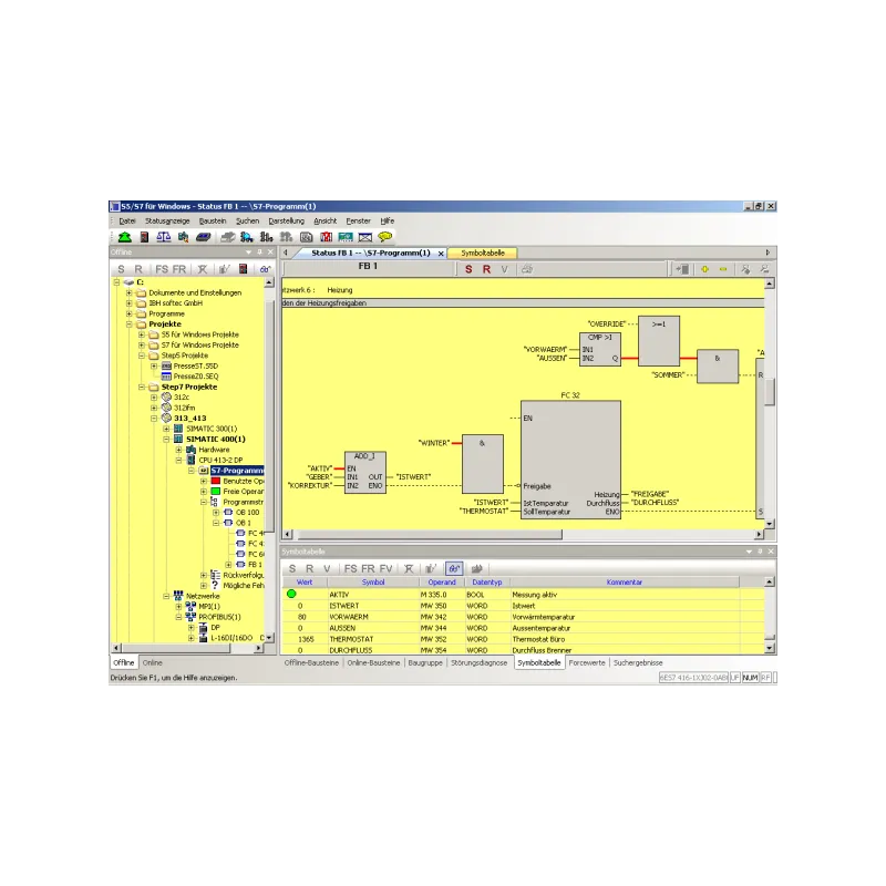
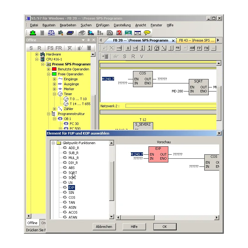
With the Oscilloscope, the diagnostic capabilities of the programming system are further enhanced. Dynamic processes can be monitored and analyzed on an integrated screen, with an adapted appearance of the front panel of an oscilloscope. Pointing to I/O signals with a virtual test probe is sufficient to monitor multiple signals within the virtual oscilloscope. The recording of signals can be stopped at any time to perform a more detailed investigation of the machine failure. In addition to observing the I/O signals, the status of the local variables can also be observed at a defined position of program execution, simply by pointing to the variable with the test probe in block status. This is only possible thanks to the integration into the S5 for Windows programming system. The recorded data can also be saved for further investigation, for archiving purposes or to send the information by e-mail. With S5 for Windows, multiple segments can be displayed in the statement list of status display representations, function block diagram and ladder diagram. The CPU status function provides information on the interrupt stack, the block stack and the system data. S5 for Windows allows calling COM packages. Communication with a PLC can be established via a USB adapter. The Step Sequence Programming of the G5 for Windows (now included in S5 for Windows) is a tool for easily programming sequential steps (sequencer control) within a STEP5 PLC program. A step sequence programmed in a step sequence block (SB) is formed by steps and transitions. The logic of transitions is used to enable the next step. The graphic G5 for Windows for programming step sequences supports linear sequences, alternative branches, simultaneous branches and jumps. The steps are displayed with boxes. There is a differentiation between an initial step, a permanent step and a selective step. The initial step is used for an unconditional start of the step sequence. The instructions of a permanent step will always be executed even if the step indicator is not active. The instructions of a selective step will be omitted if the step indicator is not active. The transitions are displayed as lines. The next step will only be executed if the logic of a transition is true. With a simultaneous branch it is possible to branch up to eight (8) more steps. The graphic display of steps and transitions can include comments. With the exception of the initial step, each step can be assigned a time. This could be a waiting time (delay timer) or a monitoring time (watchdog). The graphic step sequence programming G5 for Windows is compatible with the SIEMENS GRAPH5 and GRAPH5/II PLC programming package and therefore also needs the standard SIEMENS function and step blocks (FB70/71 – SB0, FB72 – SB2, FB73 – SB3). Simultaneously to the actual step sequence, the logic of the selected step or transition is displayed in a separate window. This logic can be displayed and edited in ladder logic (LAD), control system flow diagram (CSF) or statement list (STL). The size of the logic window can be adjusted. The corresponding Symbolic Library can also be displayed and edited at the same time. The size of the step boxes is adjustable to the size (number of characters per line, number of lines) of the comments used. The status display has the same design as the editor window. Active and corrupt steps are specially indicated. S7 programming To program the Siemens PLC control series S7-300 and S7-400 efficiently and conveniently, IBH softec provides the S7 for Windows software. This software can be combined with S5 for Windows or run independently. With S7 for Windows, the entire series of Simatic S7-300 and S7-400 PLC controls can be programmed. The complete S7 instruction set is implemented in the Statement List (STL), Function Block Diagram (SFC) and Contact Diagram (LAD) presentations. Of course, all online functions are implemented. The new operating concept of version 7 has been developed on the basis of the latest knowledge in the operator’s guide. The lock lists and symbolic tables, for example, can be freely arranged, can be drawn in any order from the main window to a second screen and can be automatically faded from the main window to gain more screen space. The presentation of the module parameters has also been adjusted. With S7 for Windows, the complete S7 instruction set can be displayed in the STL (Statement List) representation in the status view. The status operation is also possible in the Function Block Diagram (SFC) and Contact Diagram (LAD) representations. In addition, views of variables and symbolic tables are integrated in the status window. All installed interfaces capable of connecting to a PLC are displayed in the online view. All STEP7 projects can be edited directly without importing/exporting. Archived STEP7 projects can be opened directly. All write accesses to the PLC can be prevented by password protection. The traceability of signals (operands) is possible. It is also possible to perform cross-references on complete I/O modules and hardware or module diagnostics. Print preview and operand forcing are also implemented. The conversion of S5 to S7 programs has been optimized. It is also possible to save complete S7 projects on a memory card (depending on the CPU). Version 7 contains S7 Simulation and the convenient block comparison (BlockDiff). The functions of S7 Doctor for automated troubleshooting are also integrated. S7 for Windows allows fully automated debugging in the running PLC program. Compared to classic debugging, S7 for Windows performs all the necessary tasks during debugging and returns the reason for the stop in plain text. Unlike conventional diagnostic tools, no special adaptation of the PLC program is necessary. The OsciCAM allows analyzing movement processes by synchronizing previously recorded videos and process signals. The recorded videos can be displayed synchronously to process signals and a recorded block status of the PLC with time stamp. With the Statusrecorder, dynamic procedures can be explored by means of the subsequent analysis of the block status frame by frame. The Statusrecorder records the status of the block and displays it with time stamp, which allows the subsequent change between the STL, CSF and LAD presentations.
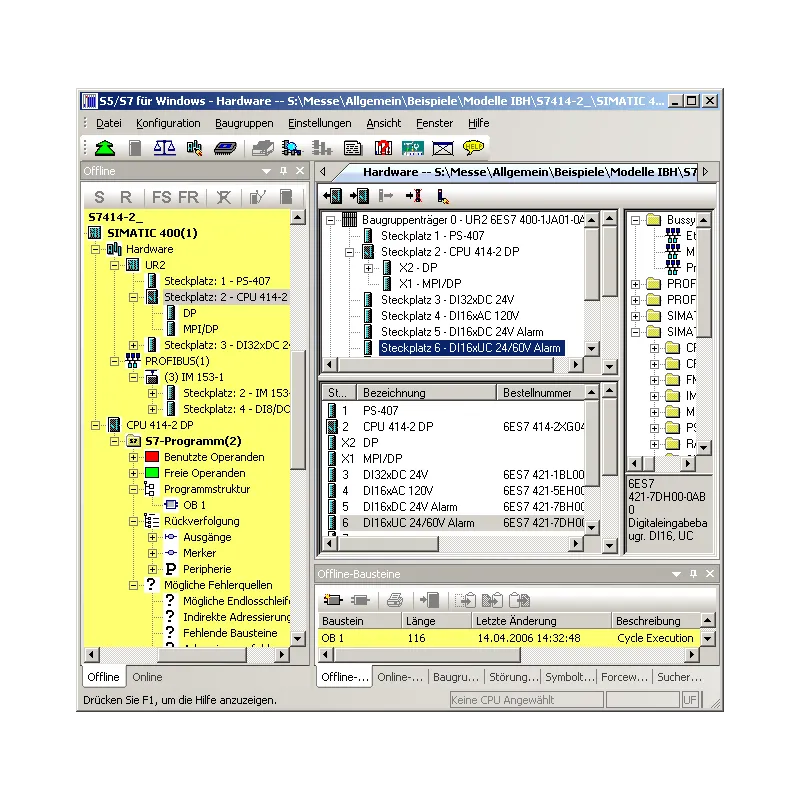
With the Oscilloscope function, the diagnostic capabilities of the programming system are further improved. Dynamic processes can be monitored and analyzed on an integrated screen, with an adapted appearance of the front panel of an oscilloscope. Pointing to I/O signals with a virtual test probe is sufficient to monitor multiple signals within the virtual oscilloscope. The recording of signals can be stopped at any time to perform a more detailed investigation of the machine failure. In addition to observing the I/O signals, the status of the local variables can also be observed at a defined position of program execution, simply by pointing to the variable with the test probe in block status. Only the integration into the S7 for Windows programming system makes this possible. The recorded data can also be saved for further investigation, for archiving purposes or to send the information by e-mail. The hardware configuration allows the parameterization of modules, the assignment of addresses and the configuration of a PROFIBUS. By clicking on the module in the configuration, a dialog box opens that allows you to configure the module parameters. In the details window of the module or CPU, the executed changes are clearly marked, to avoid unintentional changes before saving. In addition to the original Siemens PROFIBUS components, our hardware catalog contains PROFIBUS components from other manufacturers that are compatible with Siemens. The hardware catalog can be extended with files in GSD format. The hardware configuration of existing STEP7 projects can be read and edited. In addition to the offline creation of hardware configurations, it is also possible to read and edit existing configurations from a PLC. For quick debugging, module diagnostic functions are integrated. The hardware catalog is constantly updated to obtain the latest modules. These updates are available free of charge via the Internet. .
Related products


Looking for more information about this product?
Complete the form, and we’ll contact you.